Children love toys and my children love playing with their train set. At some point in time, I purchased a motorized train engine to add to their collection. Its operation was fairly simple, push the switch forward and the train engine moves forward and push the switch backward to reverse its direction. After the first few days of play, I noticed something about the way my children played with the engine. I suspect many parents can relate to giving their child a toy and finding that child playing with it in an unforeseen way. What I was witnessing was my children would turn the train engine on, play it with it off the train track and at some point, move on to the next toy that grabbed their attention. In that transition to the new toy, the train engine was left on, sometimes underneath a couch, chair, or table. Unnoticed, the train would continue to chug along until the inevitable: the battery would die. This happened with such frequency, that the cost of batteries was quickly outpacing what the cost of the train engine itself. In all this, an idea: what if the train engine turned itself off after a couple minutes? Would that offer enough time for play if the kid were to walk away? Would they mind turning it off and on again to continue playing? How long could the battery life be extended if an “on timer” were implemented?
The premise is simple: the train turns itself off after a period of time when the child becomes distracted (about 2 minutes). In case the child wants to continue playing, resetting the timer is a straightforward power cycle: flipping the switch off and back on resets the timer. To keep costs at a minimum, an inexpensive analog solution is used: a monostable vibrator configured as a one-shot timer with a motor drive; shown in Figure 1.

Configuring a monostable vibrator (Texas Instrument’s SN74LVC1G123) as a power on one-shot operation requires a couple considerations:
- Ensure Vcc is stable before sequencing input pins using RC curves
- RC components to delay input signals for one-shot operation
There are 3 pin sequences that will cause the monostable vibrator to produce a single output pulse, shown in Table 1.
Table 1 : SN74LVC1G123 Pin sequences for one-shot operation
Here, the 4th row is used as the B input has a Schmitt trigger input structure pairing well with slow transitioning signals. To delay the voltage at the inputs, a simple RC divider works (e.g. R1 & C5 in Figure 1). By using the slow rise time across the capacitor, the transition across the rising logic threshold (, Figure x; below) can be ensured after the circuit elements are fully powered. This works well for long RC time constants, but may not work if the RC time constant is on the scale of when power is applied potentially conflicting with any internal reset circuitry of the device being used.
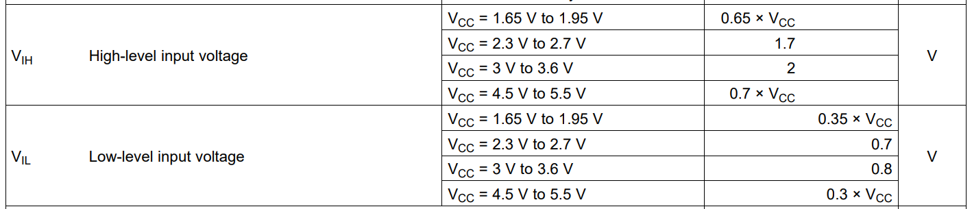
Table : SN74LVC1G23 Logic Voltage Thresholds section of EV table.
Using the threshold voltage, the supply voltage, and the time to pass the capacitor charge equation is used:
$$ V(t) = V_{o} \left(1-e^{-\frac{t}\tau}\right) $$
Rearranging to calculate our RC value:
$$ \tau = \frac{-t}{ln\left(1-\frac{V(t)}{V_{o}}\right)} $$
// Determining the RC time constant needed,
\( V_{o} = 3\,V \) (Supply Voltage; 2x AA batteries; Ideal)
\( V(t) = 2\,V\) ( \(V_{IH}\), \(2\,V\) @ \(V_{CC} = 3\,V\) to \(3.6\,V\))
\( t = 2\,ms \) (Time for capacitor to charge to \(V(t)\) volts)
$$ \tau = \frac{-2ms}{ln \left(1 – \left (\frac{2}{3} \right) \right)} = 0.00118331\,s $$
Select a common capacitor value first, \(0.1\,\mu F\) in our case, and divide to determine the resistors value
$$ \frac{\tau}{C} = R = 11833.10\,\Omega \rightarrow R_{USED} = 12.1\,k\Omega $$
$$\tau_{NEW} = 0.00132932\,s$$
Delay is slightly extended with selected R value.
Scope Capture: Vin, Pin CLR (RC Time Constant Rise), one-shot output
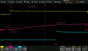
Figure : The SN74LVC1G23 One-Shot Operation
Selecting the and component values is non-trivial in this use case. The scale of the one-shot output is in minutes rather then seconds, or even milliseconds as presented in the datasheet of the SN74LVC1G123. As such, the capability and limiting factors must be considered. The output pulse period is defined by the RC time constant of and , this is seen in the application curves in section 9.2.3:
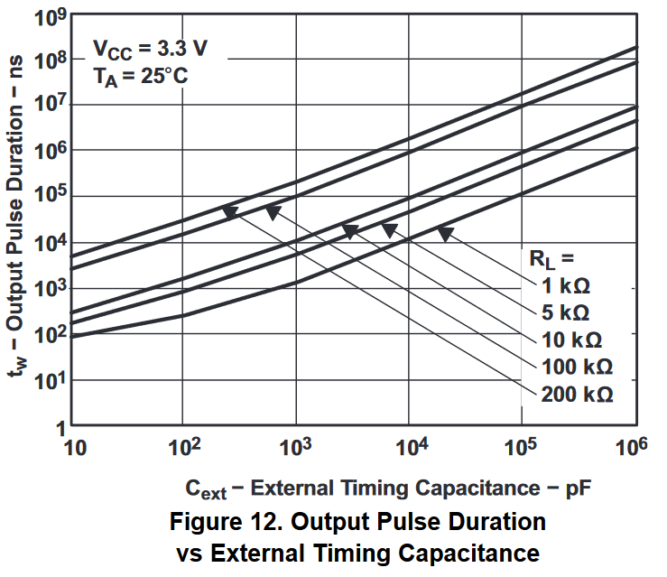
Figure : 3.3V Output Pulse Duration Application Curve
// Confirming RC time-period
\(C_{ext}=10000\,pF\)
\(R_{ext} = 1\,k\Omega\)
$$ \tau=C_{ext}\times R_{ext}=10\,\mu F\ $$
For the toy train a 120 s pulse period is used as a balance between enough time for the kids to play and the component values available in a 0603 (1608 metric) package size due to limited space inside the train assembly. When selecting component values, selecting a common capacitor value first is recommended because of limited selection compared to resistor values.
// Component value selection
\(\tau=120\,s\)
\(C_{ext}=10\,\mu F \)
$$ R_{ext} =\frac{\tau}{C_{ext}}=11.9\,M\Omega \cong12\,M\Omega$$
The order of magnitude of these component values are well beyond what is described in the datasheet. Because of this, a couple caveats come into play:
- When the switch is pushed into a neutral/off position, \(C_{ext}\) is so large it can cause significant discharge current through the SN74LVC1G123, potentially inflicting damage.
- Charge current through \(R_{ext}\) is so small, pin leakage current will likely affect the time-constant and could prevent proper operation of the one-shot mode.
The result of this work transformed how the train operated taking advantage of my children’s play behaviour. The battery consumption dropping from 1-2 pairs a week to one pair in 4-5 months. By aligning how the train behaved when powered to the way my children played, I was able to center the design more around the human factor. This benefited not only my wallet as a parent, but the planet in the reduction of batteries used.
Leave a Reply
You must be logged in to post a comment.