Author Note
This report was written for a final school project in 2016. I’ve posted that report here with a few adjustments for WordPress. Some links have become stale and thus replaced or removed from the below texted. Also, I apologize for my pretentious use of Greek letters.
Executive Summary
Measurement projection is a complicated task for a system to perform. The system designed in this project means to perform this task by taking a user configured measurement and producing a projected line of the desired length onto a surface. A number of challenges arose during the project such as accurate measurement taking, computational algorithm development and projection system development. All these tasks are examined and solutions were found to achieve the final prototype found at the end of this report.
Contents:
- Introduction
- Project Scope
- System Overview
- System Hardware
- System Software
- Project Prototype
- Future Improvement Considerations
- Conclusion
- Bibliography
- References
Introduction
Measuring is an integral part of the building and manufacturing industry. The most common tool for making measurements is the measuring tape. Often measurements are made overhead or in awkward spaces, which makes it difficult to hold the measuring tape in place and mark the desired measurement. Why is there no device that can be pointed towards a surface and project a user configured measurement onto that surface?
Project Scope
To fill this gap in technology a basic list of goals for a proof of concept device must be laid out. For this project the following goals were determined:
- Accuracy of user input to projection within 1 cm.
- 120° Forward Field of Vision, 60° on either side of a 90° reference.
- A range of operation between 1 and 30 m.
- 2 modes of operation:
- Surface Measurement, the measurement will be the circumference of the surface.
- Point to Point Measurement, the measurement will be between two points (independent of the surface circumference).
System Overview
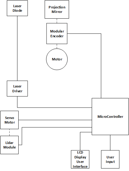
An evaluation of the system requirements determined an outline for the major components:
- User Interface
- An input interface (push buttons and rotary encoder)
- A menu interface (LCD screen)
- Distance and Angle sampling system
- LIDAR for distance measurements
- PWM controlled servo motor for angle measurements
- Projection System
- LASER for projection source
- Mirror for controlling the direction of the laser
- Motor for rotational control of the mirror
- Shaft encoder for angular feedback from the motor
- Control System
- A TI LaunchXL-F28377S development board for firmware implementation
Figure 1 describes each components logical orientation within the system; physical connections are denoted by slashed connectors.
System Hardware
Breaking down each of the blocks components is the next stage in the prototypes development. Each block within the system needs to be analyzed to determine what components are needed and the individual needs for each of the components in terms of electrical requirements and communication requirements.
User Interface
- The user display interface; providing information about the desired measure, mode of operation, and offset position (where the measurement starts)
- The user input interface, push buttons and rotary encoder for interaction with the system
The user interface was broken down into two sections:
User Display Interface
The user display interface consists of an LCM-S01602DTR/M LCD screen which operates through a parallel data bus interface. Three control signals operate the flow of data on the bus. The 3 control signals are:
- (E) – Enable
- (R/W) – Read/Write
- (RS) – Register Select
The LCD screen’s data bus can operate in two different modes, either in a 4-bit or 8-bit mode. The 4-bit mode requires fewer electrical connections (DB4 – DB7) but increases the software requirements for communication. An 8-bit mode would allow for a simpler software solution but require more electrical connections (DB0 – DB7) to the control board. The communication method selected for this project was the 4-bit mode of operation. The reason behind this is that a communication library was available for a Microchip based controller, therefore, it was easier to port the Microchip library for use with the Texas Instrument development board than to develop the communication library from the ground up. Porting the library mainly required changing Microchip PORT references to TI GPIO pin references.
Voltage levels between the LCD screen and the control board had to be shifted. The voltage that the LCD screen operates at is 5 V, where the control board uses 3.3 V. A simple MOSFET voltage shifter array was implemented to perform this task.
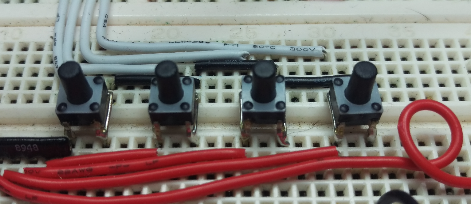
User Input Interface
The user input interface consists of five push buttons (one incorporated into the rotary encoder) and a rotary encoder for changing settings and inputting a measurement. A PCF8574A is used to connect the five push buttons to the control system through an I2C interface. The rotary encoder utilizes the EQEP_B connector on the LaunchPad development board.
The PCF8574A is powered with 3.3 V, within supply voltage requirements, for easier communication with the development board. With the supply voltage set to 3.3 V the external interrupt and I2C signals will also operate at 3.3 V removing the need of a voltage shifter between the PCF8574A and the development board.
The push buttons are configured in an active low configuration where a button press will bring the connected PCF8574A pin low. On a change at the input for the PCF8574A, the PCF8574A will generate an active signal on the pin. This signal is coupled to the GPIO99 pin on the development board, which configured as an external interrupt. Communication to the PCF8574A is performed with the I2C bus for the system; shared with the LIDAR module.
The setting of the measurement for the system is accomplished with the C.U.I’s ACZ11 rotary encoder. Rotating the encoder’s shaft will either increase the measurement value, CW rotation, or decrease the measurement value, CCW rotation. A press on the shaft performs the action of the fifth push button function for the user input interface, connected to the PCF8574A by the S1 & S2 terminals. The encoder’s terminals, A (phase), B (phase), and C (common) are directly connected to the EQEP_B connector on the LaunchPad development board. The development board provides the necessary additional components, such as, resistors, capacitors, and voltage shifting, to ensure proper operation of the connected encoder.
Distance Sampling
The distance sampling system consists of three components:
- PulsedLight 3D LIDAR module
- Custom mounting bracket
- HS-422 servo motor
These three provide the control system with the required distance measurement and the associated angle of the distance measurement.
PulsedLight 3D LIDAR
The PulsedLight 3D LIDAR module is a self-contained LIDAR measurement system. The system utilizes pulses of light, recording flight time, to calculate and determine the distance of a surface or object from the LIDAR module. The system then returns the result of this calculation, the distance, as either a PWM output or a value available via I2C communication. The PulsedLight 3D module is powered by 5 V with a 680 µF capacitor in parallel for switching current demands. Communication to the LIDAR module is performed through the I2C bus.
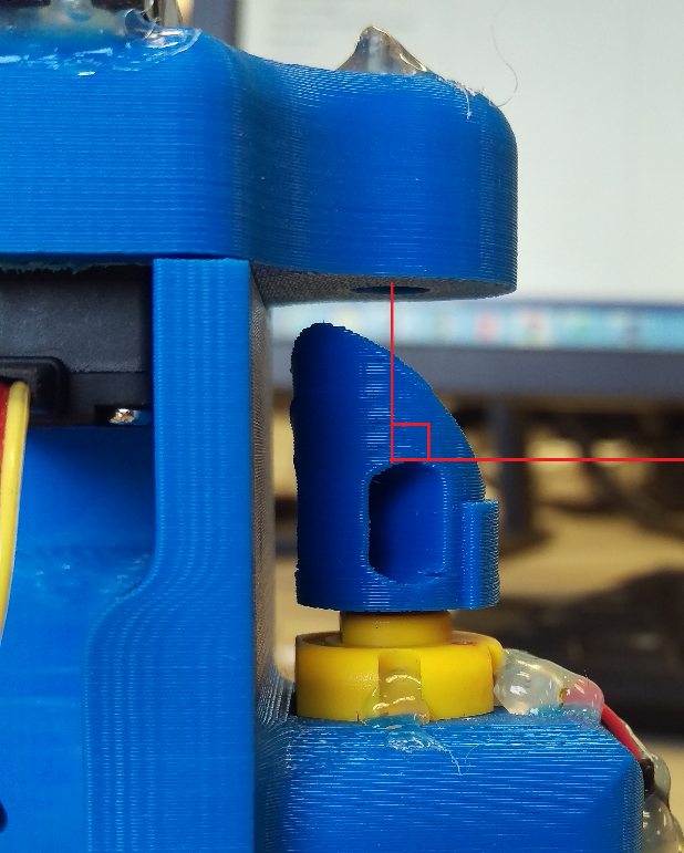
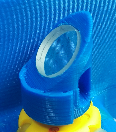
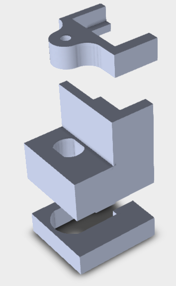
Mounting Bracket
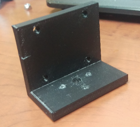
A bracket was designed to mount the LIDAR module onto the shaft of the servo motor. This bracket allows the direction of the LIDAR module to be adjusted by the position of the servo motor.
The design of the mounting bracket had 2 revisions. The initial design was a basic angle bracket in which a motor connector was to be attached. The primary issue arose from the initial design was that the shaft connector (which was screwed into the bracket) caused the LIDAR module to angle upwards away from a parallel plane to the projection plane. This resulted in the distance measurements to be inaccurate and non-useful.
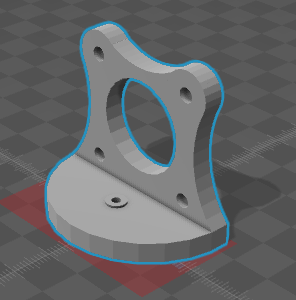
In revision 2, the shaft of the servo motor was incorporated into the design, only requiring a screw to fix the mount and servo motor together. This incorporation of the shaft into the mount solved the previous plane skewing problem. Additionally, some material in the second revision was removed to decrease the printing cost of the bracket (being 3D printed).
HS-422 servo motor
The HS-422 servo motor is a hobby level servo motor. It is used to pivot the LIDAR bracket and, therefore, the LIDAR module to allow measurements to be taken at specific angles.
The HS-422 operates from 4.8 V to 6.0 V which provides power for the internal motor and microcontroller. Positional control of the servo motor is accomplished with a PWM signal connected to the yellow connection wire.
The PWM signal for hobby level servo motors typically has a period of ~20 ms with a duty cycle dependent on each model and even unit. The duty cycle of the PWM module was manually configured to increase accuracy and reduce the error factor of the the servo motor introduced into the system.
Projection System
A custom projection solution was devised for this project. This solution utilized the following components:
- Laser Diode
- Custom Mirror Assembly
- DC Motor
- CUI Shaft Encoder
Laser Diode
A red laser diode was used as a light source for the projection system. The laser diode operates with 5 V and has an output power of ~5 mW. The diode is orientated so that the laser beam is projected straight down onto the mirror assembly. The mirror is then pulsed on and off to get the desired measurement onto a surface.
Custom Mirror Assembly
The mirror assembly is used to reflect the laser beam outwards in the forward field of vision at a particular angle. The assembly is affixed to the shaft of the DC motor as a means to control the angle of projection. A side view shows the basic idea around the LASER beam reflection for the mirror:
Multiple revisions were made via 3D printing to rectify issues that arose after the initial design such as:
- Incorrect angle of reflection
- Vibration reduction (asymmetrical design)
- Optimal reflective material
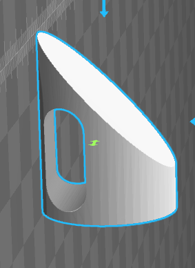
The initial design of the mirror assembly was created in SketchUp. The model had an incorrect angle of reflection which produced a parabolic projection on the surface. A new revision was designed in SolidWorks with the correct angle of reflection to 45°.
With the corrected angle of reflection, the assembly performed the task of directing the laser beam correctly, but a new issue surfaced; vibrations. Vibrations from the asymmetrical design turned the assembly into a large vibrator causing the projections to vibrate or distort. The troublesome mass is pictured here:
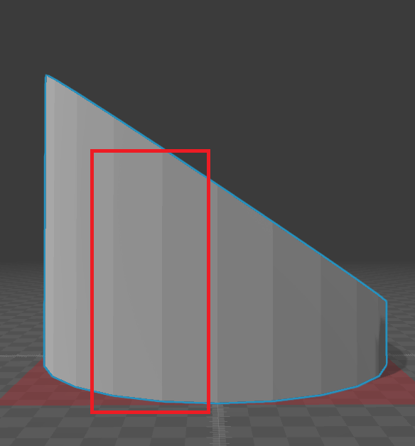
The solution to the vibration issue was to remove some mass from one side to balance the mass distribution within the assembly. A number of revisions were designed and printed with the balancing taking into consideration. The results were desirable and effectively removed the vibration effect of the asymmetrical design.
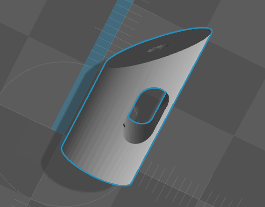
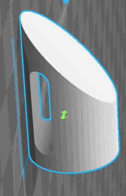
With the issue of vibration under control, the last problem with the mirror assembly had to do with the reflective material used within the assembly. Initially, a crafting reflective sticker was used, attached directly to the 45° flat surface. The issue with this was that a large amount of power was being lost when the laser beam hit the reflective material. This resulted in a very dim dot on the projection surface. An alternative craft grade material was experimented with but the results were equally undesirable.

Moving away from flexible materials a small glass mirror was incorporated into the design of the assembly as shown below.
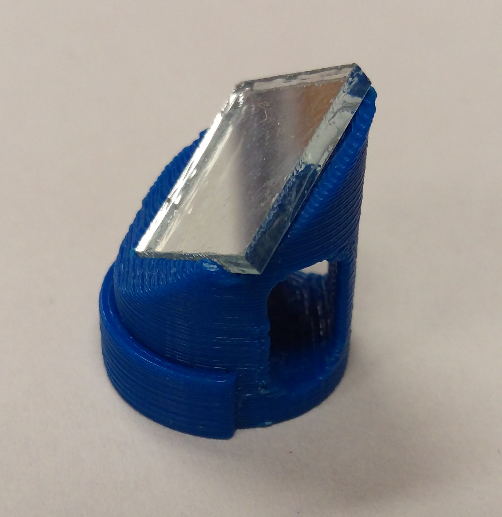
The reflection characteristics of the glass mirror resulted in a decrease to the power loss on reflection, and slight beam disruption between reflection surface and projection surface. This revision had the desirable characteristics of what was needed within the system, but the last revision was made to incorporate an Edmund Optics 12.5 mm laser diode mirror in an effort to minimize power loss on reflection.
(http://www.edmundoptics.com [Original Link Defunct])])
DC Motor
The primary function of the DC motor is to rotate the mirror assembly. An additional requirement was that there be enough shaft space available to connect both the mirror assembly and the CUI shaft encoder. The motor selected was a 1.5 – 12 V (5400 rpm @ 12 V), biaxial motor providing shaft space on either end of the motor as shown below.
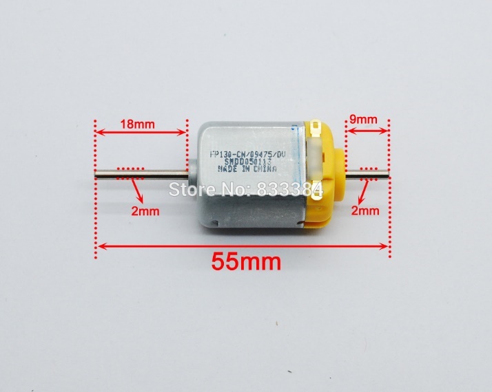
The mirror assembly was connected to the right side (9 mm in length) and the shaft encoder connected to the left side (18 mm in length) after the motor was seated into the final enclosure.
CUI Shaft Encoder
A CUI AMT112S-V rotary shaft encoder is used to provide the control system with angular position feedback of the shaft. Since the shaft is connected to both the mirror assembly and the encoder, but it is the encoder that ultimately provides the system with the angular position of where the mirror assembly is reflecting the laser beam.
The encoder operates from a 5 V supply and has a serial interface for sending the encoder commands for the onboard controller and quadrature output signals for rotational feedback. The quadrature clock outputs, phase A (A), phase B (B) and the Index (I) signal were all used to provide the control system angular feedback.
Control System
A Texas Instruments C2000 Delfino F28377S LaunchPad development board was selected for this project. The LaunchPad is based on a TMS320F28377S 32-bit MCU providing a powerful platform to develop all the software requirements for the system. Just some of the controller’s peripherals are:
- 16-bit/12-bit ADCs
- Comparators
- 12-bit DACs
- delta-sigma sinc filters
- HRPWMs
- eCAPs
- eQEPs
- CANs
The development board has 80 header pin connections (most are physical connections to the MCU) and includes some basic hardware to interface with external encoder modules and provide 3.3 V and 5 V references to assist in interfacing with externally connected hardware and components.
Final Enclosure
The last major hardware component was the final enclosure. This custom designed enclosure is used to orientate and connect all the components of the measurement and projection systems in a fixed manner.
System Software
The system’s basic operation is based around using the rotation of the mirror assembly to turn the LASER on at a particular angle and then turn the LASER off at a second angle. This variable LASER pulse coupled with the rotation of the mirror assembly will produce a line on a surface due to the persistence of vision effect*. Through measurements and calculations, the system determines the length of the laser pulse by examining at what angle the LASER should be turned on and at what angle the LASER should be turned off.
Apart from the initialization routine, the system software related to the project is segmented into six main categories:
- User interface
- Scan
- Distance sampling
- Offset compensation
- Set-point calculation
- Projection
User Interface
The user interface is comprised of two integral elements:
- The input interface
- Push buttons
- Selector encoder
- Menu Dialog (via the LCD screen)
- Measurement Input
- Measurement Offset
- Debugging features
The input interface
The selector encoder is used to increase/decrease values, initiate a set-point calculation, and return to the input menu dialog screen (if not on the input measurement screen).
The push buttons operate the dialog selection. Each push button has a unique function associated with it.
From left to right, the function of each push button is:
- Mode select (Point to Point or Surface Measurement Mode)
- Go to Offset Dialog
- Go to Debug Dialog
- Not used
Menu dialogs
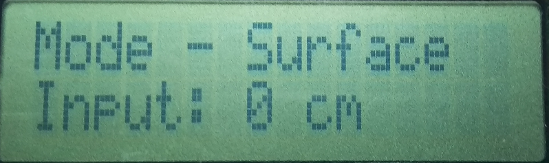
The menu dialog screens provide a simple dialog display used to provide information about the configured measurement, the projections offset angle, and an additional dialog used for testing and calibration.
The measurement input dialog (shown below) shows the current mode of operation and the configured measurement (in cm).
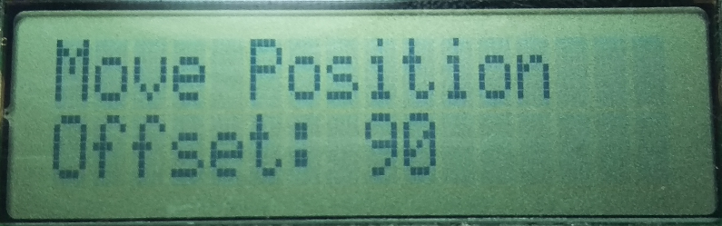
The projection offset dialog (shown below) shows the angle at which the projection will begin at. The value beside the offset is the angle in degrees. The left most point of the projection will begin at this angle.
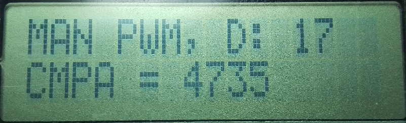
The testing and calibration dialog (shown below) was used to verify and adjust the software offset for measurements taken from the LIDAR module as well as calibrating the angle control for the servo motor. The value beside D: is the distance measurement returned to the system from the LIDAR module after an offset is applied. The value beside CMPA is the literal value placed into the ePWM module to control the servomotors angle. The CMPA value can be adjusted with the selector encoder to determine the value needed for the 10° increments.
Distance & Angle Sampling
The distance-sampling component of the software uses the ePWM peripheral to set the servomotor to a specific angle and the I2C peripheral for communication with the PulsedLight 3D LIDAR module.
Setting the Angle
The signal provided to the servomotor has a period of 20 ms, fairly standard for hobby grade servomotors, a variable duty cycle establishes the angle at which the servomotor is positioned. The position of the servomotor is recorded and controlled through a Servo structure which tracks information about the servomotor being controlled. Both the structure and the ePWM module used to control the servomotor is initialized through servoInit() as seen under the Reference section.
The servomotor used does not provide exact or linear control of the angle through the PWM signal provided to the control circuitry. To establish a more accurate positioning routine a state machine (via a switch statement) was used to control the angle of the servomotor in 10° increments. For each increment, a PWM compare value, was recorded to associate with that angle and is placed into the ePWM peripheral compare register to provide the servomotor with the PWM signal that positions the servomotor to the expected angle. In the case where an error occurs the routine simply sets the angle to 90° by default; this is the only error handling in this section of code. The associated code for controlling the angle of the servo motor can be seen in setServoAngle() under the Reference section.
Distance sampling
A distance sample is accomplished with the PulsedLight 3D LIDAR module. The module is primarily self-contained which eased the process of making distance measurements for the system. To initialize the module a reset command is issued to the LIDAR module by writing 0x00 to the internal LIDAR register 0x00; this process is seen in lidarInit() under the Reference section.
When the system requires a distance measurement to be taken the LIDAR module is told to begin an acquisition by writing a 0x04 byte to the internal register 0x00. Once the acquisition is initiated the system delays for 20 ms and then reads 2 bytes starting at the LIDARs internal register of 0x8F. The first byte contains the upper byte of a 16-bit result and the second byte contains the lower byte. The result is an integer value representing the distance from the module in cm. This sampling is repeated 8 times per distance measurement and the result averaged to artificially increase the accuracy of the LIDAR module. This distance sampling routine is seen in lidarDistance() under the Reference section.
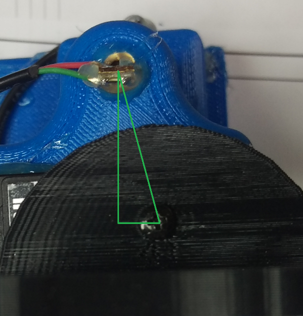
Offset Compensation
The axis in from which the distance measurements are taken is not the same axis from where the projection is generated. This offset, pictured below, is compensated for, to increase the accuracy of the projected measurement.
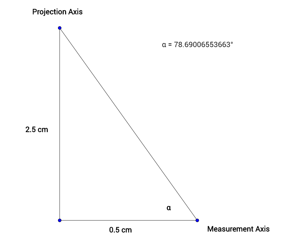
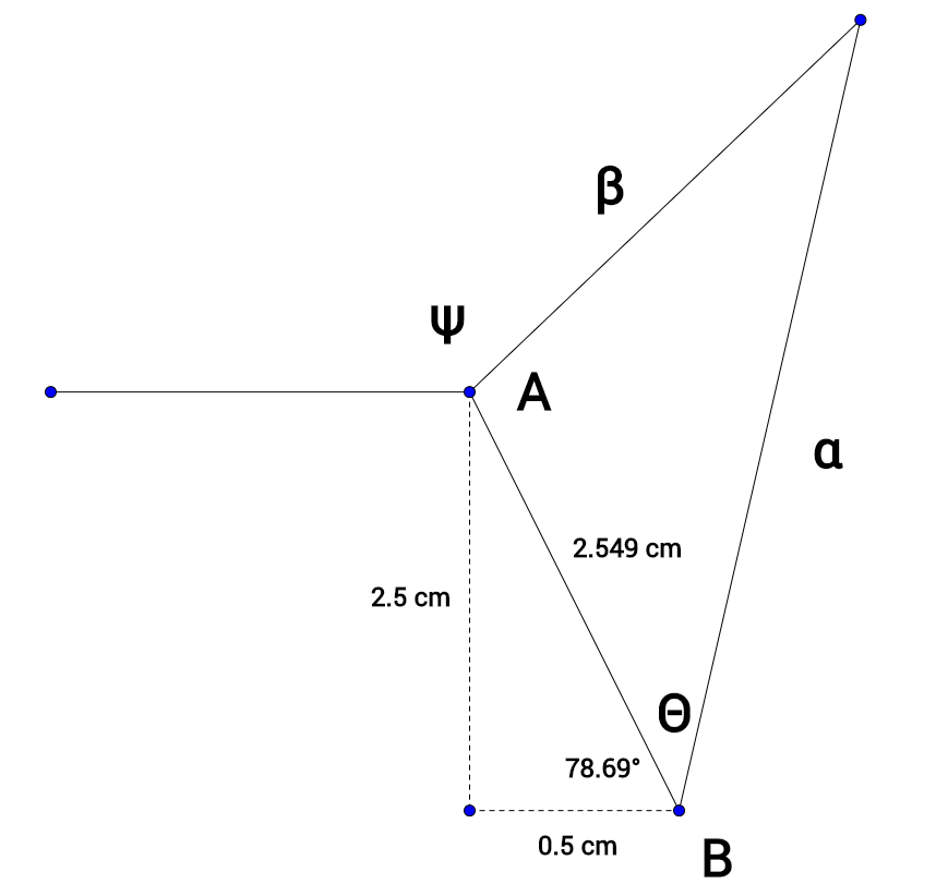
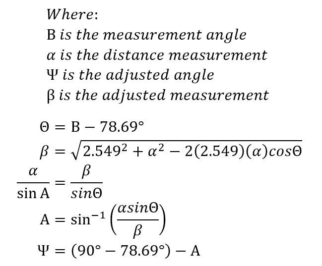
The compensation calculations take two different forms. The first form is where a measurement was taken at an angle less than 78.69° causing the measurement to cross the vertical (2.5 cm) offset depicted as follows.
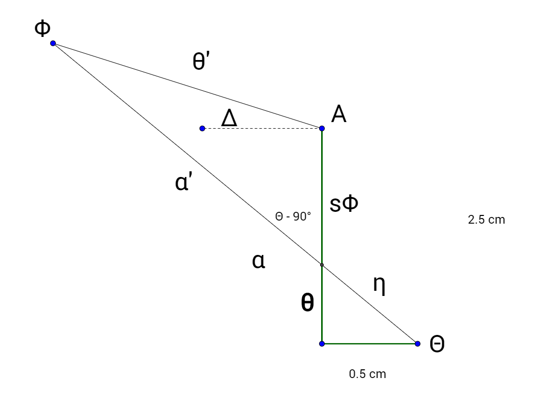
With the measurements ‘line of sight’ crossing the vertical offset the calculation to take the measurement’s perspective from the measurement axis to the projection axis is:
The second form is where a measurement is at an angle greater than 78.69° shown as follows.
Since the ‘line of sight’ for the measurement does not cross the vertical (2.5 cm) offset, the perspective calculation reduces by one-step:
The software implementation of this calculation operates on the array element (of the mPoint structure) that the measurement information is stored in. The address of the array element is passed to offsetAdjust(), where the routine determines which compensation calculation is required and performs the necessary calculations before placing the result back into the array element. The code for this implementation is seen in offsetAdjust() under the References section.
Set-point Calculation
Calculating the systems set-points to turn the LASER on and off from the user-entered measurement is accomplished through 2 routines; StartScan() and ScanEvent() as seen under the References section.
The StartScan() routine initiates a scan cycle. Which begins when the selector encoder is pressed while on the measurement input dialog. StartScan() begins the scan process by clearing any buffered variables, setting the servomotor to the initial offset angle, and delaying the first measurement to allow the servomotor to reach the correct position.
Once the initial delay has elapsed, ScanEvent() takes control of the rest of the process. The first measurement is taken at the initial angle and stored in memory. The servomotor is increment to the next 10° increment and another measurement taken. The system then calculates the surface length in-between the measurements and determines if the user measurement, starting from the offset (initial) angle, ends somewhere within this segment. If the system determines that the user measurement does not end in-between the last two measurements, both the change in angle and surface length in-between the measurements is added to a running total. If the system determines that the user measurement does end in between the last two measurements, then an interpolation calculation is performed to calculate the last angle increment for the set-point calculation.
A diagram representing this process is shown below:
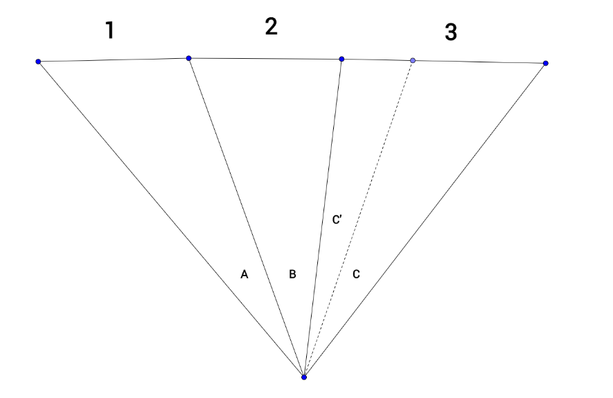
In this diagram, sides 1, 2 and 3 represent the surface in-between the measurements (the measurements are all the other sides). Angles A, B and C represent the angle increments in-between each measurement. The dashed line is to show that the system will determine that the user measurement ends somewhere within segment 3.
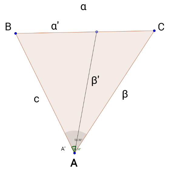
The next diagram will show the interpolation variables used to calculate the last angle increment for the set point calculation.
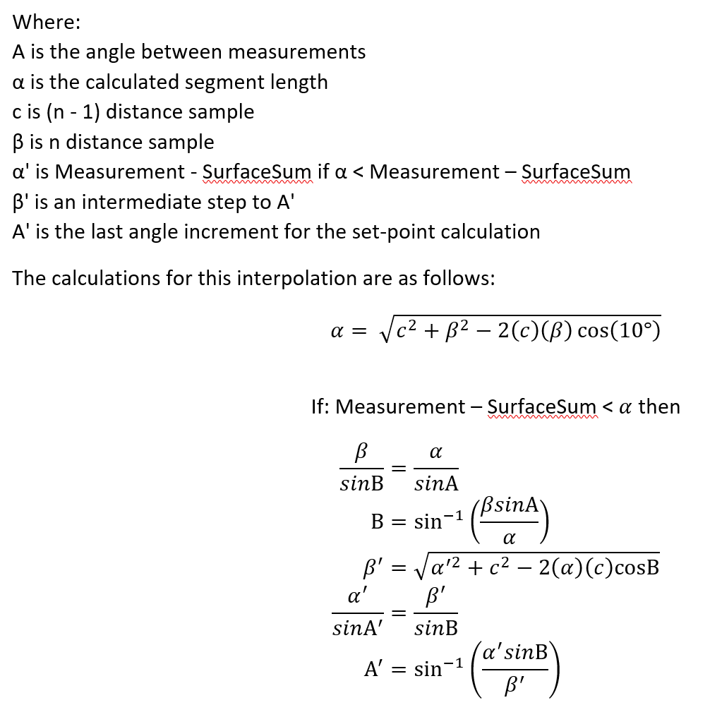
Once the angles at which the LASER should be turned on and off are determined. The angles are converted to position codes for the eQEP modules that’s attached to the shaft encoder on the motor for the projection system. This conversion is vastly more simple than the set-point calculation. the relationship boils down to:

The results are placed within an array that is used by the projection system to turn the LASER on and off at the desired angles.
Projection
The projection system software is very simplistic. It is comprised of an initialization motorInit(), as seen under the References section, and an interrupt motor_isr(), as seen under the References section. The initialization sets up the eQEP peripheral to accept the signals from the encoder connected to the shaft. The encoder produces 4096 pulses per channel which are up-converted to a total of 16384 eQEP position values per revolution. This provides the system with an angular resolution of 0.0219°.
The entire projection system, as well as the measurement angle association, is referenced around a 0° point. This means that when the position of the mirror directs the LASER beam towards the 0° angle, the position internally in the eQEP peripheral is associated with 0°. The shaft encoder is calibrated to send an index pulse at this 0° reference, which resets the position counter in the eQEP peripheral. The following diagram shows the 0° reference angle as well as the 30° lower angle limit and 150° upper angle limit, with 90° and 180° as a reference.
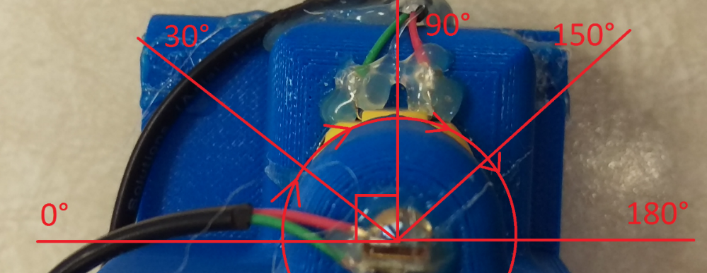
The circle and arrows show the rotation of the mirror assembly when operating. When the shaft’s rotation increments the eQEP position count to the value in the compare register the motor_isr() interrupts the controller and turns the laser on or off then loads the next compare value.
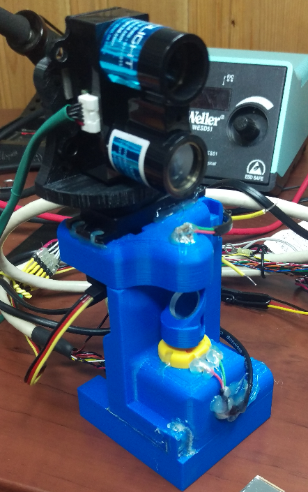
Project Prototype
The final prototype successfully met most of the goals set for the project. It provided a 120° field of vision, the range of the unit was tested from 1 m to ~3 m distance between surface and unit which yielded an accuracy within 1 cm more than 50% of the time. A point which was not met was the point-to-point measurement. This was greatly due to the angular accuracy of the servomotors positioning and the beam divergence of the LIDAR module. The surface mode of operation, covered under the set-point calculation section, was the primary mode of operation for the final prototype. The final prototype is depicted below:
Future Improvement Considerations
A number of elements in the system could be improved to develop the prototype into a consumer product. A list of potential improvements are as follows:
- Improved projection system, visibility on the surface being the primary issue
- Angular accuracy and control of the LIDAR positioning, find a new positioning mechanism
- Improved LIDAR system, to provide more accurate measurements
- Improve user interface software
- Implement a reverse operation, producing a measurement from two projected points
The list of potential improvements could extend further, but these are the primary improvements that were determined for an initial consumer level product.
Conclusion
A projective measurement tool can fill a large market gap that exists right now between tape measures and advanced manufacturing verification tools. The prototype developed in this project can potentially fill this gap by advancing the use of electronics in to consumer or middle level measurement devices. A projectable ruler would reduce the margin of error when marking measurements, reduce physical strain on workers marking measurements in overhead or awkward spaces, and reduce time spent marking these measurements. This project’s prototype shows just a glimpse at the potential of projectable measurement tools.
Bibliography
Instruments, T. (n.d.). LAUNCHXL-F28377S Overview User’s Guide (Rev. A). Retrieved from Texas Instruments: http://www.ti.com/lit/pdf/sprui25
Instruments, T. (n.d.). TMS320F2837xS Delfino Microcontrollers Technical Reference Manual (Rev. C). Retrieved from Texas Instruments: http://www.ti.com/lit/pdf/spruhx5
PulsedLight. (n.d.). PulsedLight Reference Arduino Libraries. Retrieved from Github: https://github.com/pulsedlight3d